The US DOT is very good at some things. Headlights are not one of them.
The ROW cars got nice bright H4 halogen lamps which consisted of a sealed beam bulb held in in a housing. The entire thing is not that far off of what a VW Beetle used. The housing hangs over a tab in the front fender and is secured by a screw in the bottom. Simple & effective.
The US bound cars got a more complex H5 housing with a replaceable bulb that screwed into tabs inside the bucket. Despite the higher number, they are not as bright and after 34 years of getting hit with road dirt and sunlight, the housings get cloudy and even less helpful.
The fenders are identical so it is trivial to mount the H4 lights in a US spec car. So trivial in fact that no one bothers to mention that on the internet, lol. So here we are.
The key details are to install headlight relays for the new lights and to use the thinner 356/911/912 gasket to seal the assembly to the car. The H5 gaskets are just too thick and have probably dried out anyway by this time.
The cars did not have relays originally and the high current of the circuit can break the bright/dim switch on the steering column. We use relays to let the switches control a low current circuit that switches a high current circuit. It's the same idea as your starter relay.
To do the conversion you'll need:
Wiring adapter (H5 to H4) Pelican has these or you can make one.
Euro H4 housings (find your best deal)
The thinner H4 headlight gasket
Special bottom bolt to hold it in place
Headlight relays (I used a pair of Bosch 0332209150) & wiring. You can get a full kit here https://www.jwestengineering.com/911-Headlight-Relay-Kit-74-89_p_14.html
Headlight relay sockets: Parts Express 330-075 12 VDC 5-Pin Relay Socket For Bosch Type Relay
OPTIONAL: paintable trim ring (I left my headlights with the chrome rings for now)
OPTIONAL: special lower screws to affix trim ring if you are going to use the trim ring
Part Numbers:
Headlight to fender seal (thin): 644-631-115-00
Paintable Trim Ring: 911-631-141-00
Outer Headlight Trim Screw: 911-631-132-00
Inner Headlight Trim Screw: 911-631-033-00
Pictures

Planning. Relays are mounted on an aluminum sheet and I've drawn up a schematic to follow with the wire colors and relays I am using. The gist of it is your Hi/Lo switch energizes the relays and the relays allow a high current to flow from the battery through the lights without stressing your switch. I'll be replacing this bit with a new fuse panel soon, but this was good enough for now. Recalling that power goes in the top of the fuse panel, you remove the white (high beam) and yellow (low beams) from the terminals for fuses 1 & 2 (high beams) and 3 &4 (low beams). Those are what run to the relays on terminal 85. Then the output from the relay - terminal 87 - runs to back to those terminals on the fuse box. You are just interrupting the old circuit to let the relay switch the higher current for the new bulbs. Blue/White/Black/Yellow/Red are the wires on the relay socket.
To simplify, the relay coil is on pins 85 & 86. The headlight switch energizes this, which causes pin 30 to connect to pin 87 and light the lights. The Bosch diagrams (doc below) are a little hard to read, I had hoped they would do a better job of clarifying. Highlight is the relay I used:


A2 & S4 are the referenced diagrams. The full specsheet is below.

Using the existing ground connection next to the fuse panel. That's my new lead headed off the bottom of the pic. Looks almost factory.

Adding a new hot connection to the battery with an eyelet to take advantage of the stock setup. The wire is soldered & gently crimped to the eyelet and then has shrink tubing over it. Even a temporary setup needs to be safe and reliable.

Stock US H5 housing, close up

An empty bucket. You can see the tab up top where the new assembly will hang on. The bottom tab is where the mounting screw(s) will go. The other 4 tabs are just for the H4 housing. There may be extra leads for European "City" lights. Its a good chance to clean the junk out of the housing and ensure drain holes are not plugged.
One of each

H4 close up

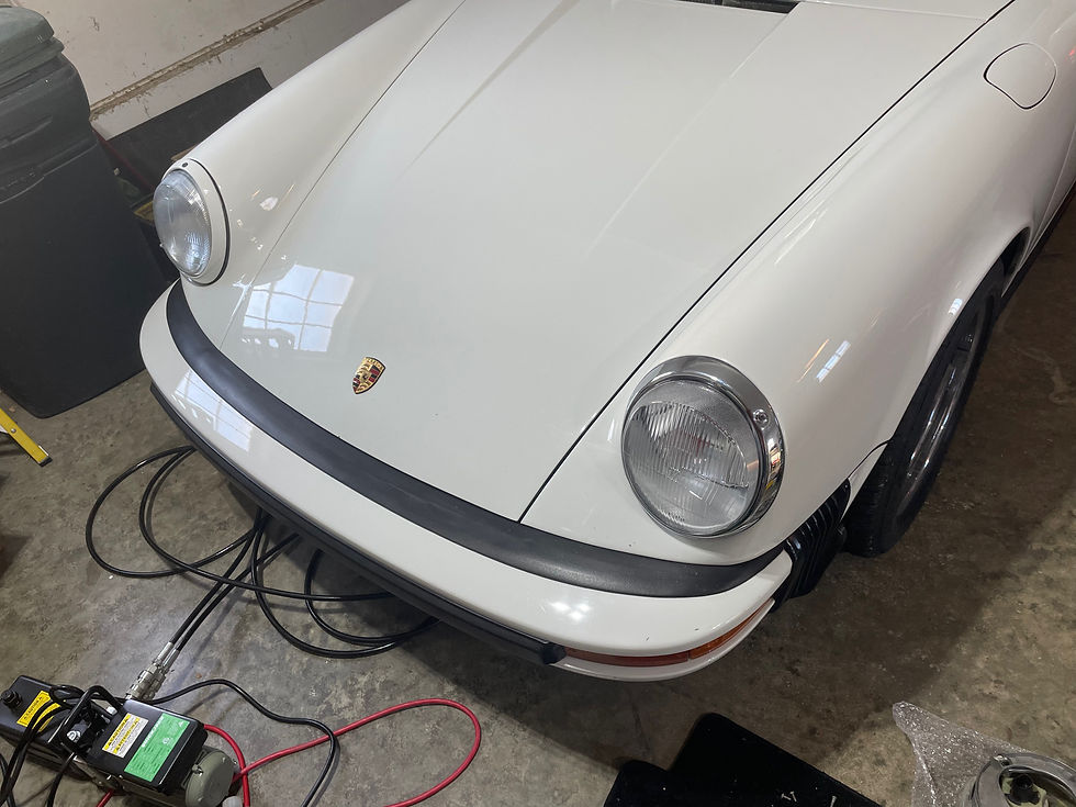
The new look. They work better, they look better.
Addendum:
After this work was completed I went driving at night and realized that not only did my low beams do almost nothing, but my high beam indicator was always on. I consulted the mighty internet and found lots of posts about the column switch going bad. I had tried the new bulbs out quickly before installing the relays. Had I fried it so quickly?
I tested the switch and in fact it was ok. The voltages at the fuse panel were way off though. I was sure the relay wiring was ok (I build & repair much more complex electronics fairly often, and I was careful here.) so I pulled off the bulbs and put the H5s in as a check. Oldest process in t-shooting: device a test, run it and evaluate the results. Identify, isolate, annihilate as my military friends are fond of saying. The lights worked properly, as did the column switch and the bright indicator. This confirmed the switch measurements, and confirmed the relay wiring. But how in the world were the bulbs wrong? Well, there is the H5 to H4 adapter. The pins on the 2 bulbs are the same and appear in the same locations. But the adapters I received swapped low beam and ground - so low beam was grounded at all times.

I labelled the H4 end to make it easier to visualize. The car side is blue = high, Yellow = low and the remaining lead is ground. You can see here that the ground lead swaps over to the low beam pin on the H4 end of the connector.
Lesson learned - never assume! I took the connectors down to the lab, cut the two leads and spliced them to the proper connections and voila! Happy headlights. Much, much better.
Resources:
Bosch Relay Data sheet:
Comments