Transformer Basics (corrected - 2.21.25)
- joepampel
- Dec 29, 2023
- 16 min read
Updated: Feb 24
Very nerdy stuff, but I am hoping I can de-mystify transformers a little bit for other casual music tech types. I am not an expert by any stretch, but I have gotten to play around with them a bit so I feel like "basics" are perhaps something I can help clarify.
Once upon a time there was a guitar player, me, who began to realize that certain parts of guitar amps appeared to have outsized influence over the sound and performance of those devices. Speakers were very high up the list, and I wound up getting involved in starting a speaker company.
Later on during some repair work and testing I realized how much of an influence the output transformer could have; something I had previously thought of as largely just functional (like a light bulb) was in fact, a lot more. And TL;DR I wound up manufacturing them for a number of years as a result of that lesson. (more here if interested)
Transformers are a very old technology, dating to the 19th century. (history here: https://en.wikipedia.org/wiki/Transformer) They work on AC signals, "transforming" aspects of them such as high voltage at low current to high current at low voltage, they provide DC isolation and they can perform impedance matching as well. All of these features are used in tube amp output transformers. You'll also see them as input transformers on many famous mixing desks, matching the microphone's low impedance (typically 150 ohms) to the needs of the pre-amp.
They are wonderfully simple, no moving parts, nothing to wear out, no supply of anything to exhaust. If someone says their transformer sounds "tired", they don't understand transformers. At their most basic they are just two coils of wire, some insulation and a core made of an iron alloy. That said, there is a lot more than meets the eye. And 5 different units systems. (here, knock yourself out: https://cse.umn.edu/irm/1-definitions-and-units) I mean, "...but each have different unit names (arbitrarily chosen and named after famous dead people, Gauss, Oersted, and emu/cm3)." ;)
But we're getting ahead of ourselves.
Some fundamental things to grasp are:
The coils have inductance - like any coil of wire does, but here it's a coil with an iron core - that changes things fairly dramatically.
The coils have capacitance between them - like any two conductors that are insulated from each other do
The coils have a magnetic field that can collapse under various conditions, like an output tube not conducting. This can sometimes cause shorts in a transformer.
Ignition coils in older autos are transformers and use this field collapse to create the sparks that ignite your fuel.
They have a hysteresis curve as their transfer function* which is unique to magnetic media. (*at least at low frequencies).
We use an iron core to keep the transformer smaller. We could build them with an air core but they would be huge which would create other issues. Capacitance rises linearly with the size of the plates - our coils here. It is also affected by the distance between the plates: https://www.electronics-tutorials.ws/capacitor/cap_1.html#:~:text=A%20capacitor%20is%20constructed%20from,as%20its%20only%20dielectric%20material.
The cores are "lossy" as are the windings. There are I^2*R losses from the winding resistance, leakage inductance between coils (causes HF rolloff), and core losses (energy lost as heat or vibration). They are still pretty efficient, but far from perfect.
the width of the hysteresis curve represents lost energy
Utility power is transmitted at very high voltages to minimize I^2 * R losses. (high V, low I) and stepped down with a transfomer near your home.
A perfect transformer would have zero leakage inductance, zero DCR in the windings, infinitely high primary inductance and a linear transfer curve.
In the most basic case, an alternating current in the primary winding induces a magnetic flux in the core. Transformers don't transform DC, they block it. The alternating flux in the core induces a current in the secondary winding. The relationship of the voltage and current from one winding to the other will depend on the turns ratio; literally how many turns does each winding have. And it will be affected by the hysteresis curve which is our transfer function. That curve is a function of the materials magnetic properties, it's magnetic "hardness" or "softness".
The transfer function ideally is a straight vertical like (not a line at 45 deg. That was my mistake). That line would have a linear characteristic and have no core losses. Everything would a consistent ratio at all frequencies. Seems easy but it's very hard to do in real life. And when we look at transformers, we get an "S" curve, not a straight line, and it is often a "thick" S curve. This is because it has "inertia" - it takes more energy than you'd expect to get it going and it wants to keep on going longer than you'd expect. (The "It" here is our flux) The magnetics term is coercivity, and it causes what are known as 'hysteresis losses' - a loss of efficiency, wasted energy. It also plays with phase since there is a time component to it. It looks like this:
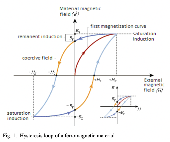
A few takeaways:
"saturation induction" is marking off the maximum flux you can have. The steel has a hard stop that point - nothing will change that. You can put in more voltage, more current, buy it flowers.. it will not make a difference. It's actually a neat feature that can be used to regulate power in some cases. (google "saturated reactor" for example). In audio, we have to watch out for unbalanced DC currents in the primary because it does not take much to saturate the core. We use "butt stacking" (all E's and all Is) to make an air gap to help protect the core in single ended designs. SE designs will also be much larger than push-pull designs of the same power level. In push-pull, the primary currents usually cancel well enough and it is less of an issue. Toroids are even more sensitive here which is why you'll see them for power but not output.
The wider the "S" is, the less linear the transfer characteristic is. Narrower is more linear. Softer magnetic materials have a more narrow curve. You want the opposite of what would make a good permanent magnet. You want really low coercivity because you are changing directions constantly, and quickly. The more energy it takes to change polarity, the wider the "S" gets. By "change polarity", we are referring to the magnetic domains in the steel.
Time, while not indicated here, is also on the X axis. The difference between that center line "first magnetization curve" at the 0 point and + or -Hc has a time component. Something was supposed to happen there, but didn't happen until a higher current level was reached. Ditto for going back down - it is slower going down. It is not unlike momentum - its hard to push the car from a stop, but once it starts to roll it is hard to stop it from rolling. In practice we'll see it alter the current waveform and present as changes in phase.
Modern magnetic steels tend to be more "square" which is better in some applications but in audio lead to a quicker or more sudden transition to saturation. Older steels tend to have a less square Hysteresis pattern. The good news is that old steels are generally still available, you can also combine different grades in a core to achieve certain characteristics and in extreme cases you could probably anneal your own to achieve a specific effect. (See "Audio Transformer Sound" below)
Adjacent: AC Bias in a magnetic tape recorder is used to overcome this issue for the media on the tape - a high frequency tone is used to get the magnetic tape into a linear region so you can record sound on to it. At low signal signal levels, it would never "get moving".


Basic Construction
EI laminations, aka 'scrapless' laminations are used in the vast majority of what you will see day to day. (pic below, this is how E's and I's are stamped) There are other shapes, such as C core which you may see in HiFi but they don't really sneak into the world of musical instrument amplification. The need just isn't there. You can see why they are called "scrapless', they lay out pretty well to get stamped without much waste.
The laminations are thin, typically 26ga or 29ga, and are shaped like E's and I's. They are made of silicon steel that is magnetically soft. (it does not stay magnetized) One E and one I make a whole layer of the core. We use laminations to reduce eddy current losses, and we insulate the individual laminations from each other with a coating to help ensure this feature works. Eddy currents are the currents that flow in the core and if the core was a block, they could flow in all directions rather than the direction we want. By using thin slices, laminations, we keep then locked in the proper orientation.
The layers are stacked various ways, depending on what the designer is trying to do, until the core will perform a specific way. The coils are wound around either a square tube, or a bobbin. Bobbins have 'end cheeks' to keep the coil from going too wide or falling off of the side, so you can wind a wider coil in some cases which can change the geometry subtlely. Otherwise there is no real difference, use whatever works for you. At OEI we used paper formers like the originals did because we were trying our best to be faithful to the original designs. It is far easier to say "we used the same thing they did" than to say "we changed the construction, but it doesn't matter".

E's and I's get stamped roughly like this. An "E" is basically 6 "I"'s wide. The middle of the "E" is 2X as wide as the other parts since it is common to both flux paths. The lighter area is left over from annealing the steel - some combination of heat treating and cooling to achieve certain goals in the structure of the metal.

The most common stacking pattern is 1:1 which is how these lams are oriented. So your stack is alternating (180 deg out) sets of E I E I E I E I E I (etc) and it makes a very familiar pattern.

The special "E" in the upper left is called a "keeper" and is placed at the beginning and end of a stack to help hold it together. The opening you get inside of the EI combination is called the winding window and the former, insulation and all coils have to fit into it.

I stacked this as a cutaway to help visualize how it all fits together. This transformer is using a cardboard former (rather than a bobbin) to hold the coils. The cutaway part is butt stacked (all Es) just for the picture.

It is important not to short the core laminations together. These are 2 different styles of standoffs used to bolt the core together tightly while not shorting it. For the same reason you do not want to scrub off any rust that may have appeared. The laminations are specially coated to avoid shorts, and you risk scraping that off. Rust does not hurt them. If you leave off the insulators you can short the core and it may vibrate more loudly and get hot.
Most of your flux is traveling through the middle of the laminations, not the outside. On some modern amps such as Peavey's the power transformer may even be welded to the chassis. This is what makes that possible.
There are various stacking patterns, sometimes known as "lacing". If a butt stacked single ended output transformer is the maximum case, and 1x1 is the minimum, there are many in-between patterns available. 2x2, 3x3, etc. The JTM45 used the RS Spares Deluxe output transformer which stacked the core laminations in groups of 10. You lose some primary inductance, but you pick up some resistance to saturation. It is like building in little air gaps because the laminations are not perfectly flat; they are slightly bent from being stamped. A specific lacing pattern doesn't guarantee a specific effect - this is happening in conjunction with the rest of the design. How much primary current will we have, how much flux is there, do we need a wider margin to protect our core material against saturation? Can we afford to lose some primary inductance?
Here are some examples:

An original Haddon output transformer in a vintage Vox AC30. You can see the core is stacked 3x3

The output transformer from an octal pre-amp Fender Tweed Twin amp stacked 2x2

A 1960's 50W Marshall stacked 2x2

A Pacific repro of the Stancor used by Trainwreck; 3 big stacks.

A couple of OEI prototypes, 2x2 and 3x3. It was very interesting hearing the same coil structure on different cores and even on different steel alloys.
My transformer is humming
Power transformers in particular can be noisy sometimes. The laminations in any transformer are subject to a phenomenon called "magnetostriction", they are literally changing shape as the signal goes through them. If you feel brave, disconnect the speaker on an amp, crank up some music through it (use something silent like a phone or cd player) and you will hear a very quiet and tinny version of it from the output transformer (as long as it lasts!). The power transformers will hum at 50 or 60Hz depending on your utility line frequency. This will get worse if the bolts are loose or if too much current is being drawn by the circuit. If your power transformer is hot and humming, it is either sized wrong or you have a circuit fault.
Basic Testing
'I think my output transformer is toast"
This comes up so often in on-line troubleshooting it's almost a meme. Someone, usually new at this stuff, runs into symptoms they don't understand or cannot explain and so they decide it must be the transformer. Then they take DCR measurements to try and support their guess. Usually a mistake piled on a mistake. Yes, they can fail, but it is relatively uncommon compared to other components. And generally your failure is not a marginal "it sounds funny", it usually just doesn't work or causes some big issue - the fuse blows, no sound at all, etc.
Open turn - either the primary or secondary has had too much current (heat) and has gone open. Transformer no longer functions and DCR is infinite for at least one winding.
Insulation failure - Most likely between primary and secondary (the primary has 2X your B+ in it) and this can blow fuses or if the amp is able to idle it may become unstable under a signal.
Shorted turn - (goes with #2 above) Here is where your DCR might be off by a lot between the two sides of the primary (for example) so the transformer works but sounds bad because the load impedance (turns ratio) is way off now.
Turns Ratio
This is handy if you are not sure which taps are which. Lots of people do this lots of ways. I like to take my signal generator, put a 400Hz sine into the secondary and turn up the signal until I read 1V across it. Then I measure the voltage across the primary. If I have 20V there, my turns ratio on that tap is 20:1. It keeps the voltage low and has been plenty accurate for me. Most common guitar amp output transformers are going to run somewhere from 10.45:1 (100W Marshall) up to around 44:1 (Like a Super Reverb or Bassman) give or take. You should not see any huge or tiny numbers on a normal day. A 100W Marshall which has a 1,750 Ohm primary running into its 16 ohm tap has a turns ratio of 10.45:1 which is about as low as you'll see. The square of the turns ratio X the load gives you the reflected impedance on the output tubes. For example, the 15.81:1 ratio for the AC30 is (15.81)^2:1 or 250:1 and our load isn't 1, it is 16, so 16*250 = 4.0K reflected on the primary.
Primary Impedance
If you know that you have 4, 8 & 16 ohm taps, you can put a resistor of that value on that tap and then measure across the primary with an LCR meter to read the reflected value. It is actually pretty accurate. If you don't have a 16 ohm resistor, sub the next closest thing and then correct for the difference to find out what you would have read if it was 16 ohms. (for ex).
DCR:
Make sure the transformer is out of the circuit and just measure with a DMM.
Measure from each primary lead to the center tap, and then from primary lead to primary lead. They two halves should add up to the whole. The two sides will never match exactly for a very simple reason - as you wind the coil, each layer is longer (bigger) than the prior one. Designers will mix things up to get them close, but it's not worth the trouble to get them too close because at the end of the day that DCR difference will be swamped by the impedance. Eg: if one side is 70 ohms and the other is 80 ohms and the primary imp is 3,400 ohms - 10 ohms does not matter. Even in class B operation at 1,700 ohms that 10 ohms still doesn't matter. Beyond that the tubes won't be matched that closely.
Primary InductanceYou won't be able to measure the primary inductance accurately; it depends on current in the winding exciting the core at low frequencies. You need an inductance bridge and a powerful signal generator like an old HP 200AB (designed for audio, it can put out 10 watts!) to make up for core losses. It's more accurate to back into it by operating the device and then sweeping it with audio signals and finding your half power points.
Leakage Inductance
You can measure leakage inductance pretty well even with a cheap LCR meter. You simply short the secondaries together and measure across the primary. It should be zero, (reflecting the short!) - but it won't be. The lower number the better the transformer is likely to handle high frequencies.
Interwinding Capacitance:
Short the primary wires and measure the capacitance to the shorted secondaries.
The Williamson Output transformer measurements paper (below) has a lot of great info for taking measurements.
Guessing at purpose and power
Core size is a good proxy for power, aka VA. Also a good proxy for low frequency response.
Your turns ratios will fall into patterns; a tube amp power transformer might have:
120V in
Secondary at 315V (315/120 = 2.6:1 turns ratio)
Secondary at 6.3V (19.0:1 turns ratio)
Secondary at 5V (24:1 turns ratio)
A typical output for a 50W Fender that uses a 4K primary might look like this:
4K Primary into 8 ohms = 4000/8 = sqr(500):1 = 22.36:1 turns ratio
4K Primary into 4 ohms = 4000/4 = sqr(1000):1 = 31.62:1 turns ratio
4K Primary into 2 Ohms = 4000/2 = sqr(2000):1 = 44.72:1 turns ratio
The most common "50W" size core we tend to see is a 1.5" stack of 1.25" lams, meaning the tongue (middle of the "E") is 1.25" wide. This covers the 50W Marshalls, & the AC30. The 50W Fenders like the Bassman & Super Reverb seem to stick with 1.25" stacks of 1.25".
A Vox AC30 which is running 4K into 16 Ohms has a turns ratio of: 4000/16 = sqr(250):1 = 15.81:1 and the core is about the same size as a 50W Fender or Marshall.
Don't they get wound to crazy wide tolerances?
Well, no. Copper wire is expensive and no one is throwing you freebies. If anything your winder is probably looking for less costly ways to hit your design specs. There are some very simple reasons that imp ratios can be off, and they really have more to do with how the wire winds.
Let's say you have 1,600 turns on the 4K primary mentioned above, and you need 4,8 & 16 out. And let's say your secondary wire gives you 40 turns per layer. Ultimately this is what is happening - it is a 3D puzzle where you wind wire around a bobbin and that has implications. Current handling gives us wire ga. Wire ga and core size gives us turns per layer. Voltage gives us insulation thickness. The winding requirements give us the total turns, which we use to calculate how many layers we need. You have to then check to make sure this will all fit. If it doesn't fit you get to try try again. (there are spreadsheets, thankfully)
16 ohms is a turns ratio of 15.81:1 so if you had a 1600 turn primary winding, you would have 101.2 turns on the secondary. .2? Hmm. And if your secondary wire gives you 40 turns per layer, you're going to have 2.5 layers of wire. How are you going to get that 1/2 a layer to sit nicely? And then you're probably going to lose that ".2" of a winding (1/5 of a turn), so you will be a little bit off. These things can add up, getting the wire to wind nicely and then getting rounding errors that are multiplied by the turns ratio. That .2 turns multiplied by our turns ratio is 3.162, then multiplied by 16 (ohm load) gives us 50 ohms of "error", and we really haven't done anything wrong. Luckily 50/4000 is only 1.25% error.
The 8 ohm secondary has a ratio of 22.36, so it will need 71.55 turns. 1.79 layers of wire
The 4 ohm secondary has a ratio of 31.62, so it will need 50.6 turns. 1.27 layers of wire.
You can see how each tap can wind up a little off, and depending on what happens with those partial layers and partial turns you can have different responses. It doesn't take much.
The good news is the secondary is really 101.2 turns total, (not 3 windings here) with taps for 4 & 8, which helps with the layering.
You could also take that secondary and not do the full 40 turns per layer, and add a layer (or more) to achieve something simpler. There are lots of "tricks" such as reverse winds or bifiliar winds to help adjust for various situations you come across. The more designs you see, the more of these you will see in action. The links to CJ's notes are really great for this too. (below)
Trying to simplify things
One easy way to think of a transformer is it is a gearbox. It just has a ratio, and you can go forwards or backwards and that ratio doesn't change. If my turns ratio is 20:1, 400V on the primary will become 20V on the secondary. Conversely, if you apply 20V on the secondary you will have 400V across the primary. It's not a step up or step down - it is both. It depends on how you use it. In the same way the source impedance and load impedance are "reflected" back across the transformer. Your 8 ohm speaker looks like a 4k load because of the turns ratio, and your tubes look like an 8 ohm source. (leaving negative feedback out for now).
Note on materials:
A typical 50W output in "Guitar Amp World" is made of a 1.5" stack of 1.25" laminations. The AC30's output is as well. Edcor will sell you M6 grade laminations; there are other grades of steel you should probably try, to hear the differences.
26ga is .018" so that is roughly 83 lamination pairs. (1 E, 1 I per layer)
29ga is .0136" so that's roughly 110 lamination pairs (" ")
I mention this because if you purchase a "String" of 29ga E-125 laminations from Edcor, you will receive 660 EI sets, or enough to construct 6 output transformers, or about $40 of cost per core.
I have included some links below, but for those wishing for more practical 'how to do it' guides would do well to head over to Group DIY and search on threads with CJ on them. He has rewound all kinds of transformers and does nice write-ups with photos.
References
Edcor's very cool blog: https://edcorusa.com/blogs/hi-tek-gadgeteer-notes/
CJ Tears down a 50W Marshall: https://groupdiy.com/threads/marshall-mk-ii-fifty-watt-output-transformer.60904/
CJ's diagrams for various Ampeg Output Transformers: https://groupdiy.com/threads/ampeg-transformers.74182/
CJ 's basic materials Guide to help you roll your own: https://groupdiy.com/threads/diy-output-transformer.57735/
RJ Keene's guide to designing Output Transformers: http://www.geofex.com/Article_Folders/xformer_des/xformer.htm
Randy Aiken explains it all: https://www.aikenamps.com/index.php/output-transformers-explained
Links to books (RDH, magnetic materials, transformer design, local files, etc)
Radiotron Designer's Handbook: http://www.tubebooks.org/books/rdh4.pdf
Magnetic Circuits and Transformers (MIT Press) https://babel.hathitrust.org/cgi/pt?id=uc1.b4154646&seq=7
Transformers for Electronic Circuits: (Book) https://archive.org/details/transformersfore0000gros_edi2
Magnetic Circuits and Transformers, MIT Press (also see their OpenCourseWare for current info. https://archive.org/details/magneticcircuits0000eest
Lamination Steel Grade Specs: https://www.copper.org/environment/sustainable-energy/electric-motors/education/motor-rotor/production/proc03/process_03_31.php
Terms:
Annealing: https://www.tlclam.net/annealing-process/
Magnetostriction: https://en.wikipedia.org/wiki/Magnetostriction
Select Suppliers
Edcor - parts and materials: https://edcorusa.com/collections/materials
Temple Steel https://www.tempel.com/en/ (Edcor sells laminations made by Temple)
Thomas & Skinner https://thomas-skinner.com/
Bahrs die and stamping (Covers) https://www.youtube.com/watch?v=GVBTSG2rs4M
Commentaires