Another small amp whose pricing has gone bonkers since the pandemic.
Build vs Buy is an easy one now.
Same basic drill as the 5E3, board, chassis, bring them together & wire them up. The mid 60's amps have a different chassis and more parts, more complexity. I had to swap out my original power transformer because the voltage was too high and it ate the first pair of tubes. Things happen.
Make sure you can mount the chassis in your cabinet before you start out. I use the chassis as a drilling guide.

I like to lay things out, measure and then mark it off with painter's tape, re-check my markings and then drill. Same for the handle. Measure, tape, measure and drill. This is the only part of the process that makes me nervous.

Measured, marked and drilled... how did we do?
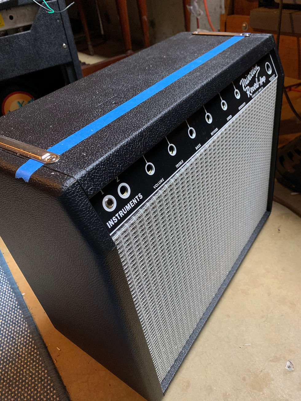
Looking good. Lets build an amp!

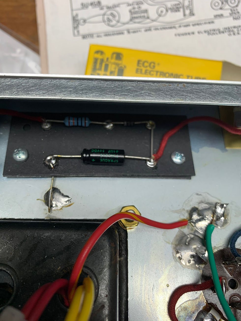
Start out with your empty boards and your layout. The "blackface" nearly all have a main eyelet board and a secondary bias supply board.
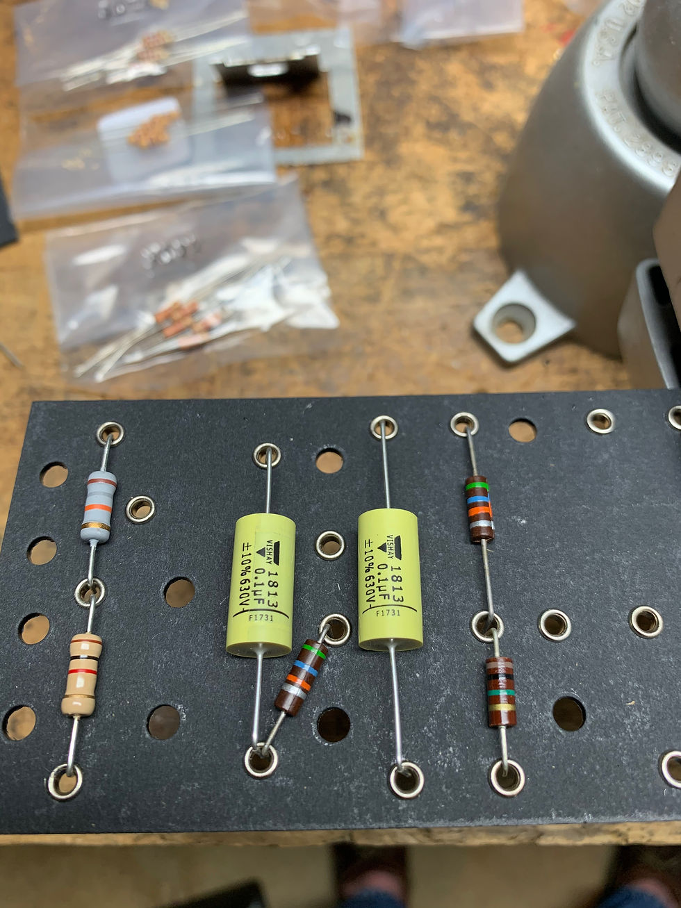
Start stuffing the board. I like these Vishay 1813 caps, they are a great size and quality.
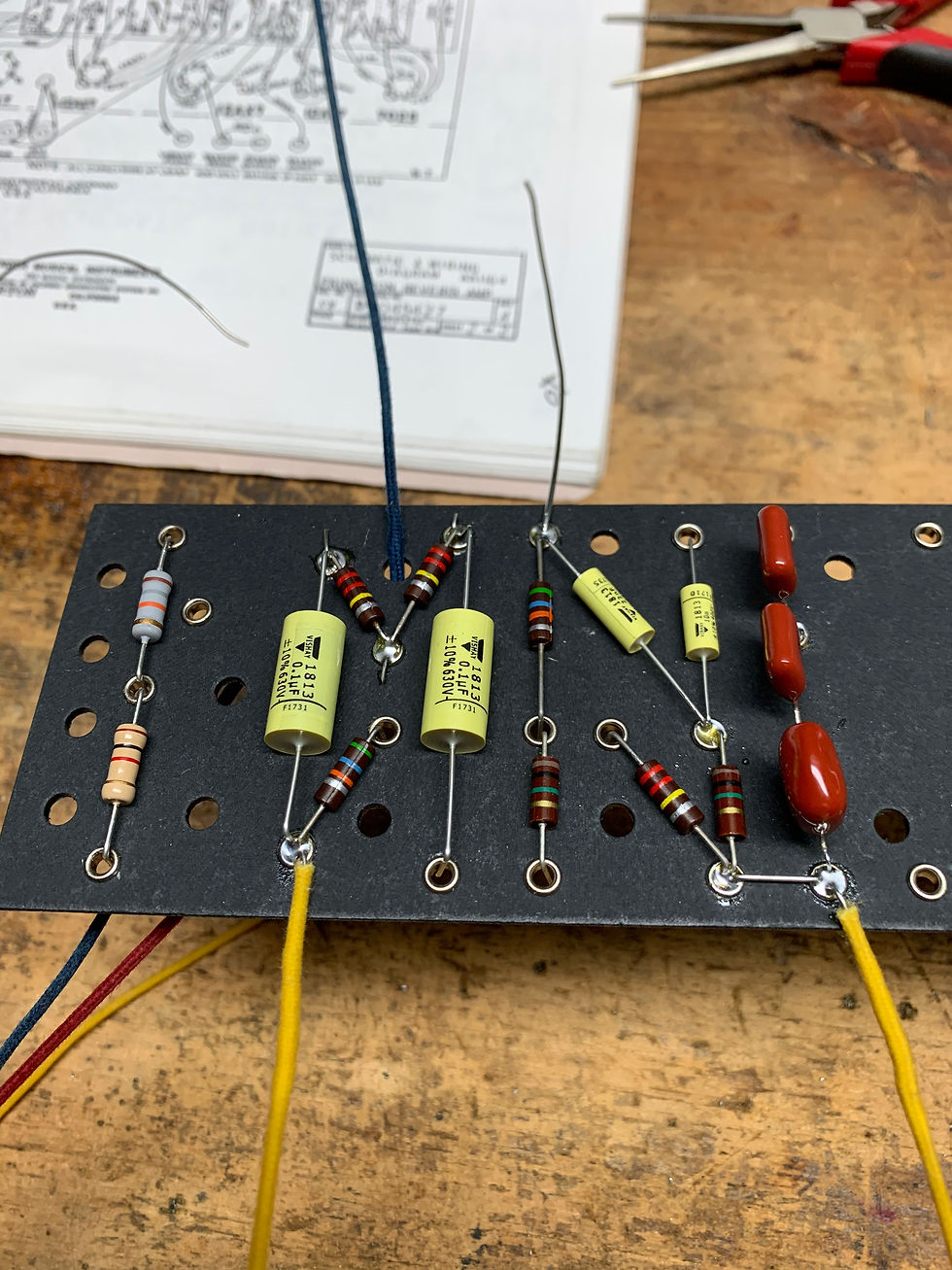
As I finish specific areas I add the leads and solder them. It helps me keep track of where I am. Some folks like to use highlighter on a copy of the layout. Find whatever works for you. Your solder joins should look like these - clear, shiny and not like bubbles - they should flow.

The board is nearly done here. Just really missing the leads that run on top. I use clipped off capacitor leads for the ground connections. Or if they are really long, I use push-back braid heater wire, and just remove the insulation. For the hard to find colors, I purchase white and then color it with sharpies. You can buy most of it these days pre-colored though.
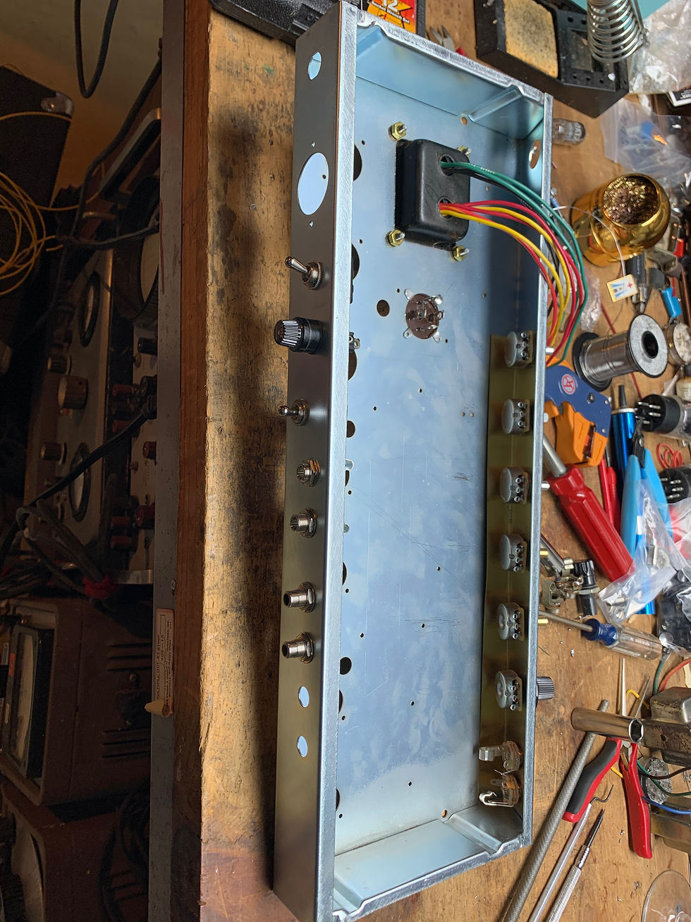
Start mounting the hardware on the chassis.

Hardware is nearly done. I had an old Princeton output transformer around so I used that.
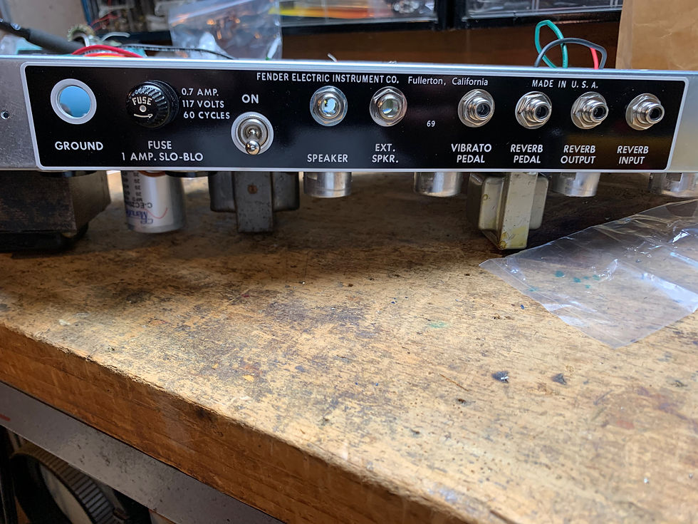
The hardware holds on the front and rear panels. I usually wait until we're nearly done to mount the panels so I don't scratch them up
Drop in the board and start wiring once all the hardware is on and you have soldered the filter cap (if you are using the stock style). I found some 60's era Ajax caps so I used them in the first stage for the tone controls. This is probably one of the most important spots in the circuit.
Soldering to the chassis is not hard but needs specific tools and a different approach. Here is how it works:

That is a Weller 85W iron for stained glass work. It's under $40 online. The key is the mass in the heater & tip - they are very large. When you touch the chassis, the chassis will heat sink the iron so you need mass to keep the heat where you need it. You also need flux paste, and a tip tinner/cleaner. For some reason people think you need 100's of watts - you don't. I promise! You need mass. Higher watt soldering guns etc. will just cook the component and do a poor job of soldering to the chassis.
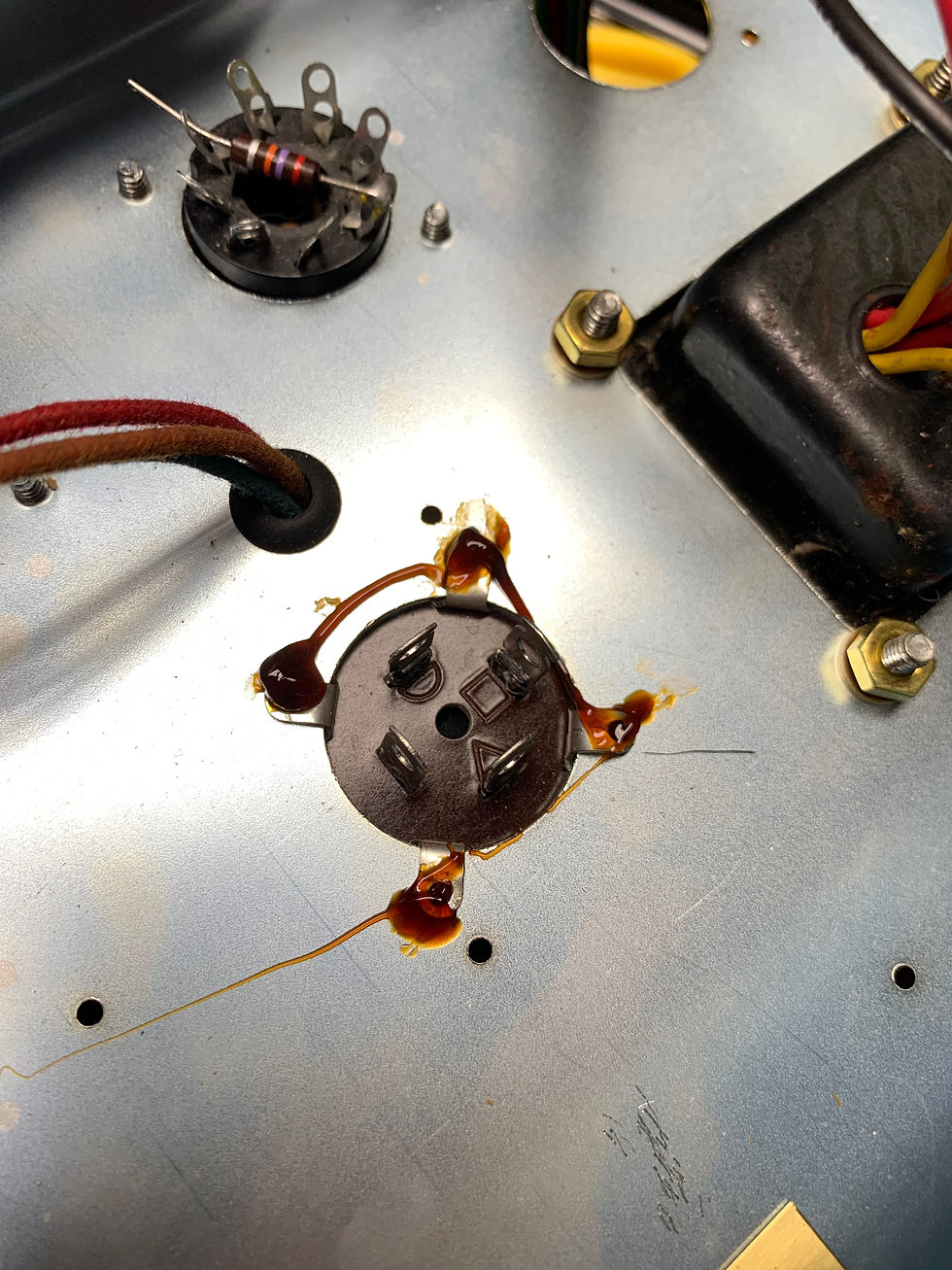
Scuff up the chassis, bend the pins down to make a good mechanical connection and put flux down where you will be soldering. Pay attention to to the orientation of the multi-cap. Those symbols indicate the order that the sections are built as- eg: first, second etc. It has to do with heat dissipation. I found my copy of the guide so here it is!

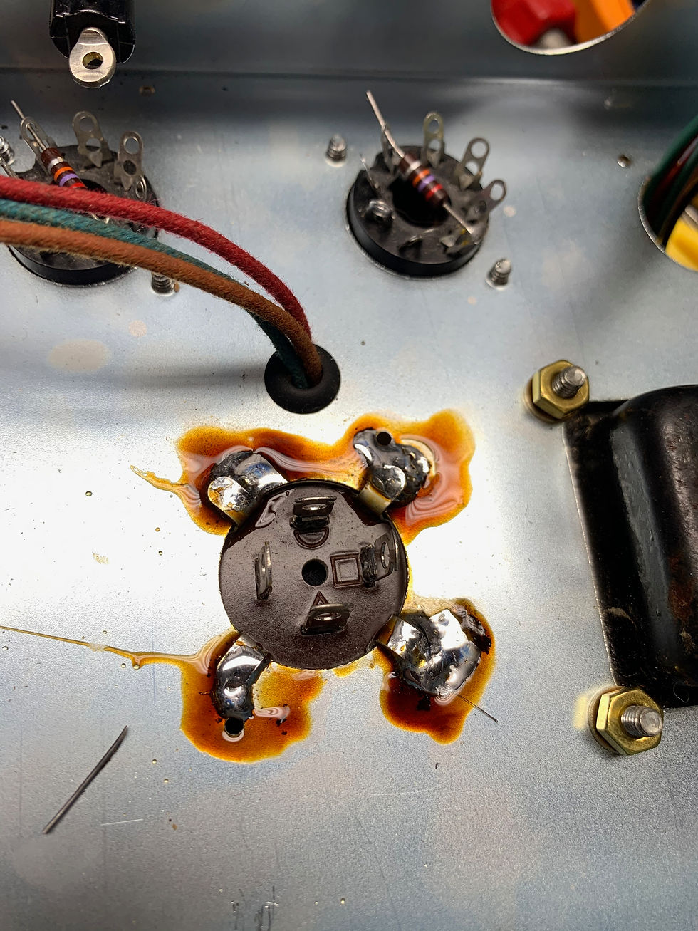
Next, use your BFI heat the work and melt the solder to make a nice shiny & smooth connection. You will see it start to flow. Heat it only as long as you need to in order to get a good connection. You do not want to cook the capacitor.

Clean off the flux with iso alcohol and q-tips or paper towels.

I like to check the connections afterwards, just to be sure.
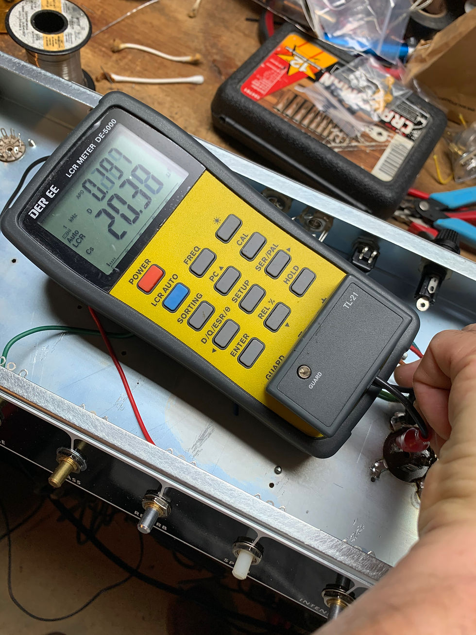
And I check the cap to make sure I didn't cook it. Still 20uF. Life is good.

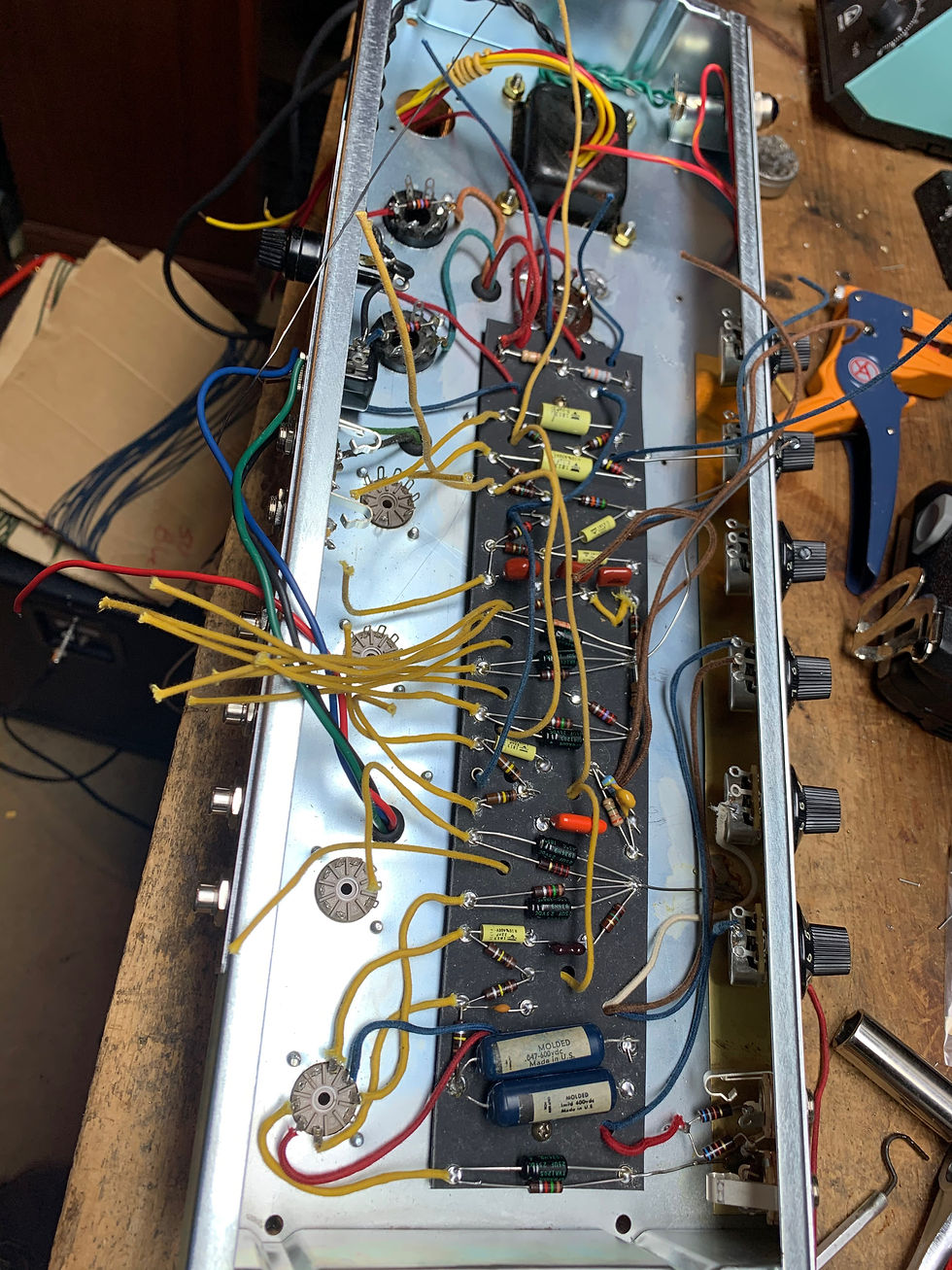
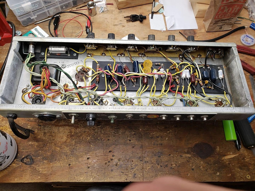
Now we can drop in the board and get wiring!
Some other chassis grounds.

Another item that trips folks up is the strain relief on the power cord. These are strain relief pliers. Beg, buy, borrow or whatever but use them. They make it much easier and don't mess up the plastic strain relief. It is key to have the right size strain relief and the right diameter power cord.
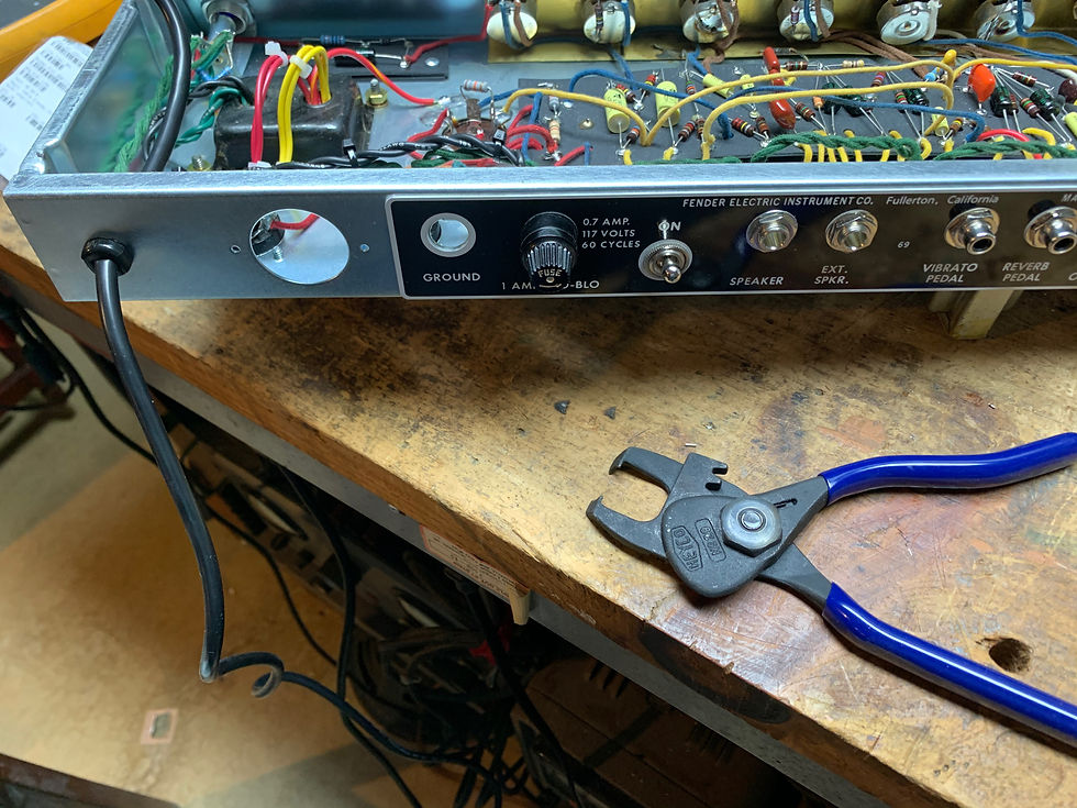
Here is the power cord mounted properly; the green ground lead should be longer than the black and white leads such that if the cord is pulled out, the ground is the last connector to go.

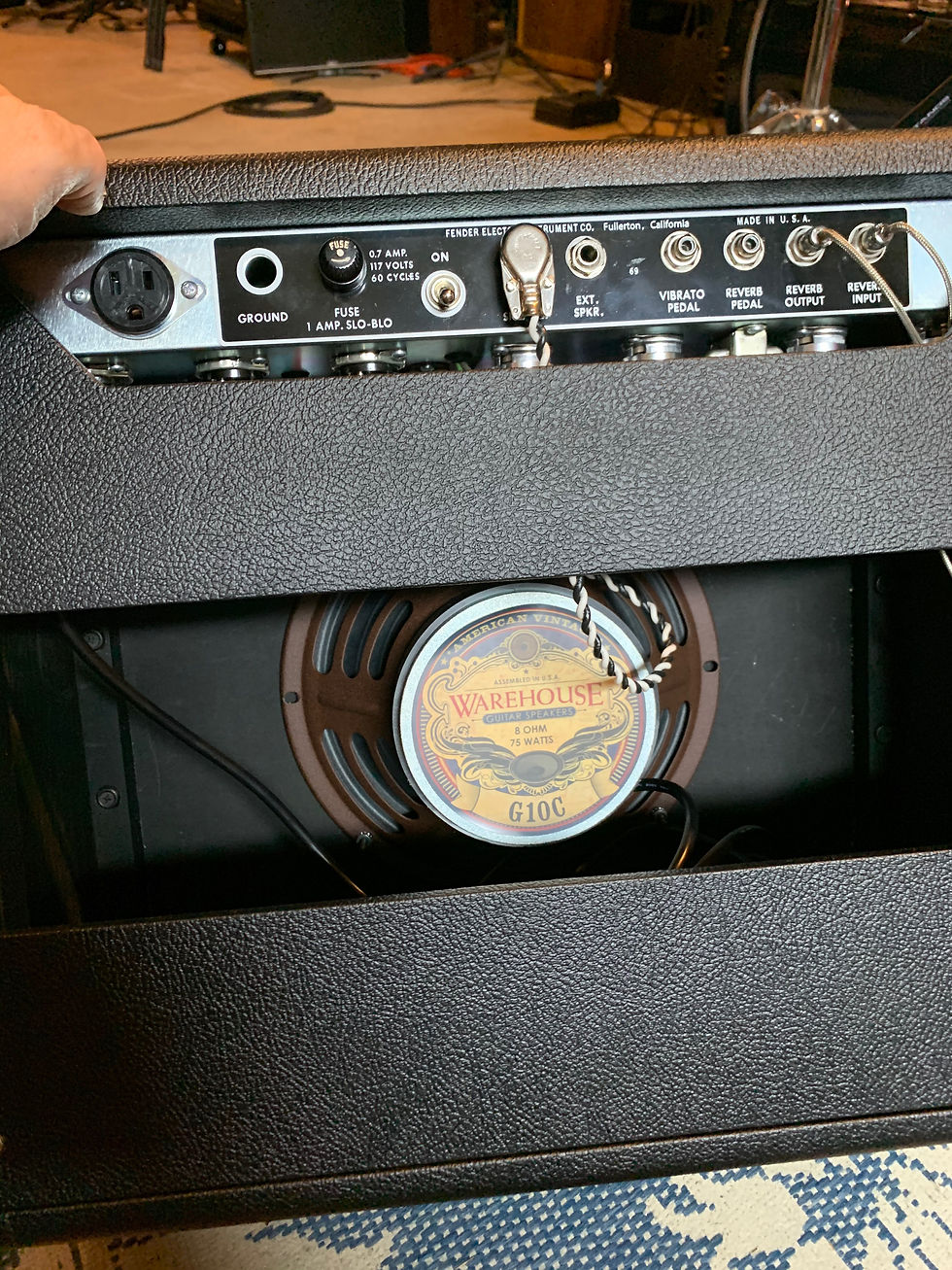
Speaking of safety grounds, I found an OEM style utility plug with a proper 3-prong socket, so I wired this up to run my pedal board. Hard to find and prices are all over the place ($10-$100... no kidding!) just be patient and you can find them.
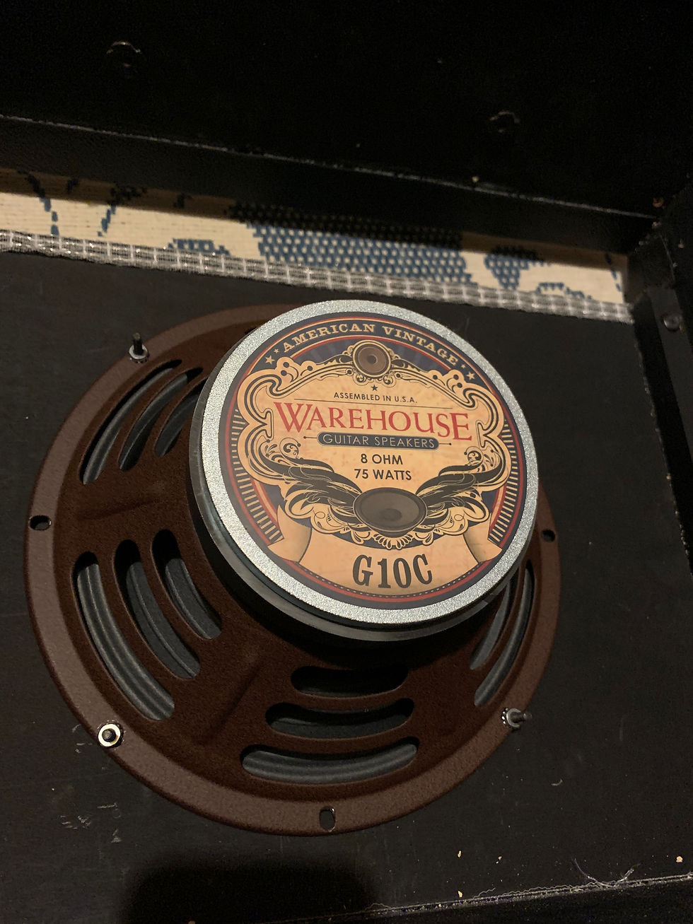
A great speaker recommendation from Lyle Caldwell. Takes a beating, sounds great, very efficient. It's a winner.
An original 70's era Princeton Reverb for comparison.

Ours. The solid core push-back braid wire is much neater looking. Modern capacitors are also generally smaller which gives a different look. It probably helps that I don't have the shop foreman timing me while I do this! (I don't know that they did, I'm just joking)

All buttoned up and ready to go.
Commentaires