As with any hobby, there are the parts you think you need to know, and then all the other stuff you learn along the way. The hard knocks, in some cases. I am going to try and share a few things I think I learned along the way on the off chance it can help someone.
Even if you buy a kit, there will be tools and materials it is assumed you will have access to, so I have listed the ones I would not want to build without.
Tools (pics below)
* A good temperature controlled soldering station. Not a $20 pencil from "offshore discount". We want to solder at ~750 degrees reliably. (I use a Weller WES51)
* A chisel tip for that iron - the larger tip is still small enough to solder an eyelet, but has enough mass to solder to the back of a potentiometer without issue. I like the Weller stuff because Mouser has an entire page of accessory parts including various tips. You can tweak to your hearts delight. (Weller is now part of Apex tools btw)
* Stained Glass 85W Soldering Iron - These are inexpensive and have a huge heating element and chisel tip so you can solder to the chassis easily. I use this one.
* A volt-ohm meter, often abbreviated VOM (for analog) or DMM for newer digital units. You will need AC & DC volts up to at least 500V (preferably 1,000V) , and resistance measurements of at least 5 Megohms. (my Fluke meter goes up to 50M)
* Fine needle nose pliers (flat - no cutter) - for bending or straightening leads, getting into tight spots.
* Flush cutters (aka dykes or wire cutters)
* Panavise or equiv. Yes you can build without one, but they come in so handy to firmly hold work while you solder/assemble at all kinds of angles. #fanboy
* Strain Relief Pliers - to install the AC cord properly (and remove them for repairs)
* Dental pick - for making room in eyelets during repair/replacement or assembly. For pushing leads into place.
* Heat Gun - to shrink your shrink tubing
* Nut drivers - for tightening nuts on 1/4" jacks, pots, etc.
* Mini screwdrivers - for tightening the grub screws that hold your knobs in place. Some knobs may use tiny allen keys for their grub screws.
* Pilot light Wrench - these are usually custom made but get one if you can find one.

* Automatic wire strippers - this set (pictured) is the best. Thank you Doug Hoffman for this recommendation. They have been a huge help when working with PVC wire. They stabilize the wire while you strip the end and are adjustable for how far back the wire is stripped so it is easy and repeatable.
* Solder sucker - to remove old solder from eyelets, turrets and pots. Some people love the blue plastic "Soldapult"; I swear by the smaller Aluminum bodied Jensen-style units. Pick your poison. Mouser carries this one that looks also pretty good. Make sure you can get spare tips for whatever style you go with.
* Metered Variac or Light bulb current limiter - to control your first power-up. Because mistakes happen. Incandescent bulbs will get harder to come by in the future so I would recommend buying a Variac and adding an inexpensive current meter to it. If you can, try to use an analog meter; they will be easier to read if something changes suddenly which is what you want.
Materials
* Shrink tubing in a variety of colors (to match the leads you are putting it on)
* Spare wire - because sometimes you'll run out when building a kit.
* Blue (non-marring) Painters tape - to hold wires, etc. in place until you can solder them. Great for putting buss wire in place, or connections to pot cases.
* Tip cleaner for your iron above - not a sponge please! (makes the tip rust! Thanks to Robert Hull! ) use the 'brass wool' type.
* Tip Tinner - " " every now and then to get the tip back to nice and shiny.
* Paste Flux - for soldering to the chassis
* Good quality 60/40 solder (I use Kester)
* Tie wraps - in Black & White at a minimum, and in various sizes to bundle wires together, etc.
Assembly Tips
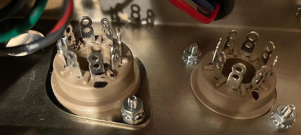
* Mark off Pin 1 of your octal sockets with a sharpie to help you get oriented as you connect things to them from beneath. It is easy to miss when they aren't well marked or visible - and upside down. Some sockets have it clearly marked, some don't. YMMV
* Use painters tape to hold things in place when you solder. The actual connection should be physical - not depending on solder, but sometimes wires do not want to stay put. If you have to make a bus across the back of the control pots, tape is also your friend.
* Always cut your wires a little long. Save some room in case you make mistakes or need to do repairs in the future. I usually go about a cm longer than I think I need with pushback braid wire to make sure I am accounting for the section I'll be stripping off, and then routing the lead after it is connected. Making stuff too tight just leads to problems in my experience. YMMV.
* Clean up the eyelets - If you're building a kit with eyelet boards (Fender style), you should run over the board with 0000 steel wool to take off any oxidation on the eyelets. Usually the plating is in good shape, but not always. Oxidation will stop solder from wetting properly.
* Build the input jacks outside the amp - another obvious one, but it does get missed. Use the chassis as a jig and assemble the input jack assembly outside the amp and then install it as a unit. On some amps it is a bigger help than others. An JMI AC30/6 is probably the most complex.
* Assemble all of the hardware (for tweed - don't install the input jacks on the chassis) and then build the board with flying leads outside of the chassis and then bring them together as a final step. It is much easier and cleaner, and the hardware is often a lot easier to access with other stuff in the way. Install the input jacks after the board is in. This may seem obvious but I see pics on line quite a bit of people assembling the boards inside the amp. With a British style amp this can work, but with a tweed fender chassis you will run out of curse words.
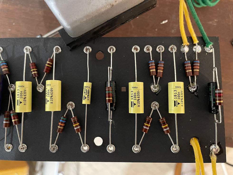
Assembling the eyelet board while holding it in a Panavise. Leave the leads long and bend them into the eyelets prior to soldering and then clip them afterwards. This will give you a good mechanical connection which won't be too hard to remove during a repair.
* Test - I like to assemble the power supply first with filament wiring and bring the amp up to make sure I have not made any big mistakes. The power supply is where the highest voltage & current are and can cause the most damage. Knowing it is solid is a big bonus going forwards. With some kits they have you do the filaments and AC wiring last to keep the assembly a little easier as well as making it hard to shock yourself. Nothing wrong with that approach either.
* Lead Dress - For Fenders, follow the factory layouts as closely as you can. Generally speaking, any time you have to cross leads esp audio and power, do it at 90 degrees to minimize any interference. Be very careful around the phase inverter where you have the speaker outs and the feedback lead as well. If there is a lead going to the front for a presence control, be very careful with this as well. The high currents in this area contribute to sensitivity to HF feedback. All wires get magnetic fields as a function of current flow, and the OT secondary has the most current. If your amp feeds back on power up, check your phase through the phase inverter circuit as well as the output transformer primary. There are factory drawings with errors here. (it happens) Then check your lead dress.
Pics

85W Weller 'stained glass' soldering pen for chassis work, paste flux, tip tinner, tip cleaner.
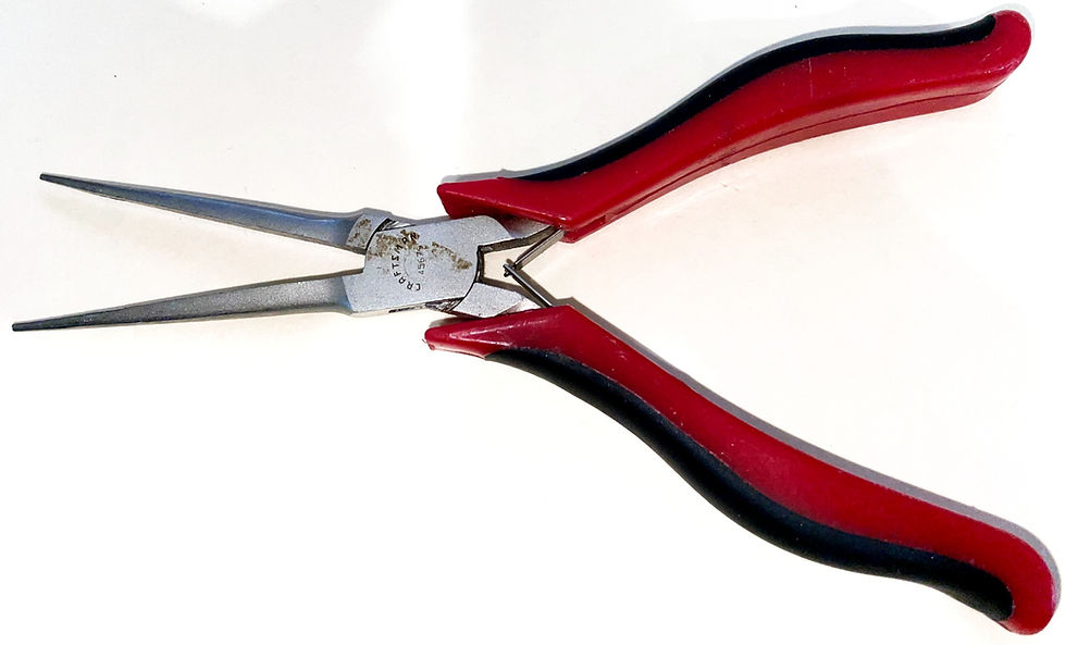
Fine Needle Nose Pliers

Flush Cutters - keeping the ends as small and pointy as possible allows you to trim leads inside of the tube sockets and other tight spots.
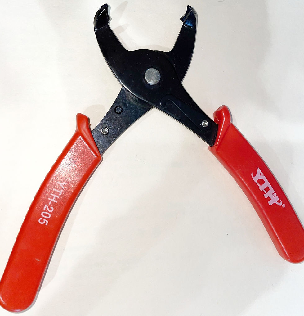
Strain Relief Pliers

Dental Pick - I use the "crook" end to push things into place and the pointy end to clear holes in eyelets.

Fender-Style Pilot Light Wrench

Automatic Wire Strippers

Solder Sucker

One kind of metered Variac. The current meter lets you detect short circuits almost immediately - at very low voltage, so you can shut off power easily before any damage occurs. I've used this one for ~30-odd years. You can add a current meter to any Variac. Eico, Genral Radio and others all made metered Variacs. Check Hamfests & ebay for used ones.
Basically, with the Variac you plug the new amp in, you start with the voltage on zero and then you slowly bring it up. If you have a short in the power supply, the current meter will go full scale very early on and you can power off before you do any damage. Or if you get the amp up to full power but something goes wrong you will see the current rise (and probably hear hum intensify) and can shut down before there is damage.
A lightbulb limiter is different in that it limits the current into the circuit to prevent damage. Once the amp under test is acting normally, you need to take it off of the limiter to operate it though - they generally will not work properly on a limiter.
With the Variac, you can just operate it while plugged into the Variac.
Either can be a very effective tool for trouble-shooting.
Comments