The mother of all guitar amps, originals still sell for north of $10,000 64 years later.
So build vs buy is once again, a no brainer.
They are perhaps 3/4 of the way up the complexity scale; their use of negative feedback for the presence control makes lead dress fairly critical if you want the amp to be stable. The only tougher vintage amps I think are the "brown" era Fenders with the fancy tremolo and also the Vox AC30 which had essentially the same circuit. Most of the chassis in an AC30 is the trem, not the amp! The key is to keep the transformer secondary leads as far from the front panel as possible, and watch the wiring to the presence knob. In the JTM45 I built I goofed here, so I want to call it out to help others not goof.
The "why" is simply that the magnetic fields around the wires relate back to current flow, and nowhere is there more current flow than in the transformer secondary where we are going to drive speakers. 40W into 2 ohms implies (using P = I^2 * R) that 40W = I^2 * 2 so I = 4.47 Amperes. That is some real current, and it can definitely interfere with other parts of the circuit.
I used the best transformers I could find, and for the critical speakers I found 4 used Hammond P10Rs from 1959 & 1960 that I then had re-coned by Vintone. The only difference is my speakers are silver instead of GM Green like the Jensens (it's a 1960's GM 6 cyl valve cover color, per Ted Weber who was a GM Powertrain engineer.) I can live with that.
This has become one of my favorite amps to take to gigs because of its great combination of light weight, plenty of volume and fantastic sound. I love my AC30, but it is 75lbs, which is like 400lbs at 3AM when I am getting home. It's also 58 years old and worth some money; this home brew amp can be replaced if it falls out of the van.
I built this back in January of 2015. Since then I have replaced the plate resistors in the phase inverter (the carbon comps seem to fail here a lot for me) and replaced both output coupling capacitors - as they both broke down - with Vishay 1813s. I got lucky and found an affordable pair of matched NOS Tung Sol 5881s years back, so that is what went in the amp - the same tubes it shipped with in 1959. It sounds pretty great.
Starting with the cabinet, I put on several coats of uncut shellac to give it a darker patina, more like it had sat in a smokey bar for a few decades.
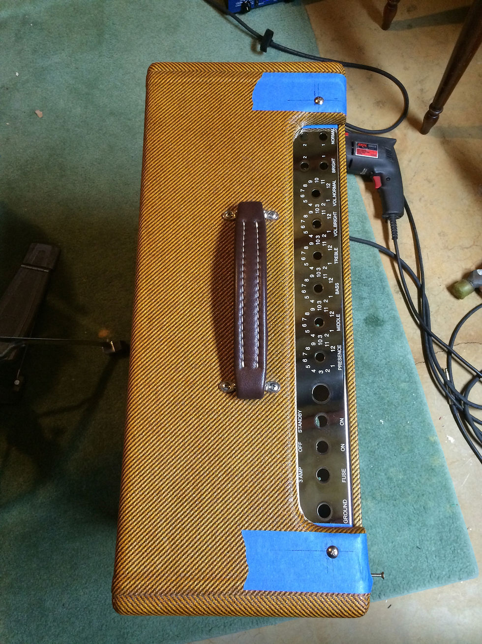
Then I got to work lining up the chassis.

I used the chassis as a template and painters tape to give me a writable surface. Thankfully, the chassis use slots to give you some wiggle room.

check the dimensions a couple times and now we're ready to drill, almost

Give it a nice start with an awl to ensure the drill isn't going to wander and mess up my cabinet.
And it fits! We will add the 3rd bolt later after the power transformer has been mounted. I use an L bracket and grind it down so it will mount on one of the power transformer bolts. This gives the heavy side of the chassis the support it needs.
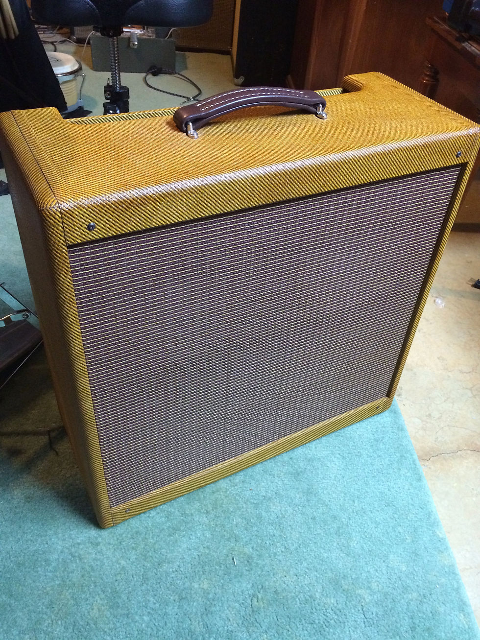
Here is a nice look at the dark finish. It is distinctive.
Now that we have a place to put the chassis, we can get to work on it.

Test fitting all the hardware. I added a bias adjustment pot on the chassis so that took a little trial and error to make sure there was room for it.

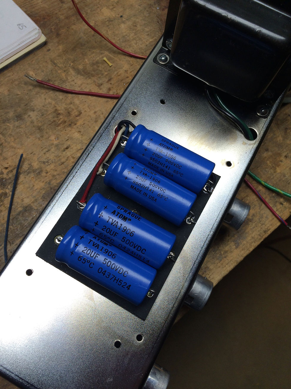
Original 5F6-A's soldered the filter caps into the doghouse (the cover). I went a bit more traditional here, putting them on an eyelet board under the doghouse. I lined it up so I could drill the chassis and make sure the mounting screw would not interfere with the main eyelet board.
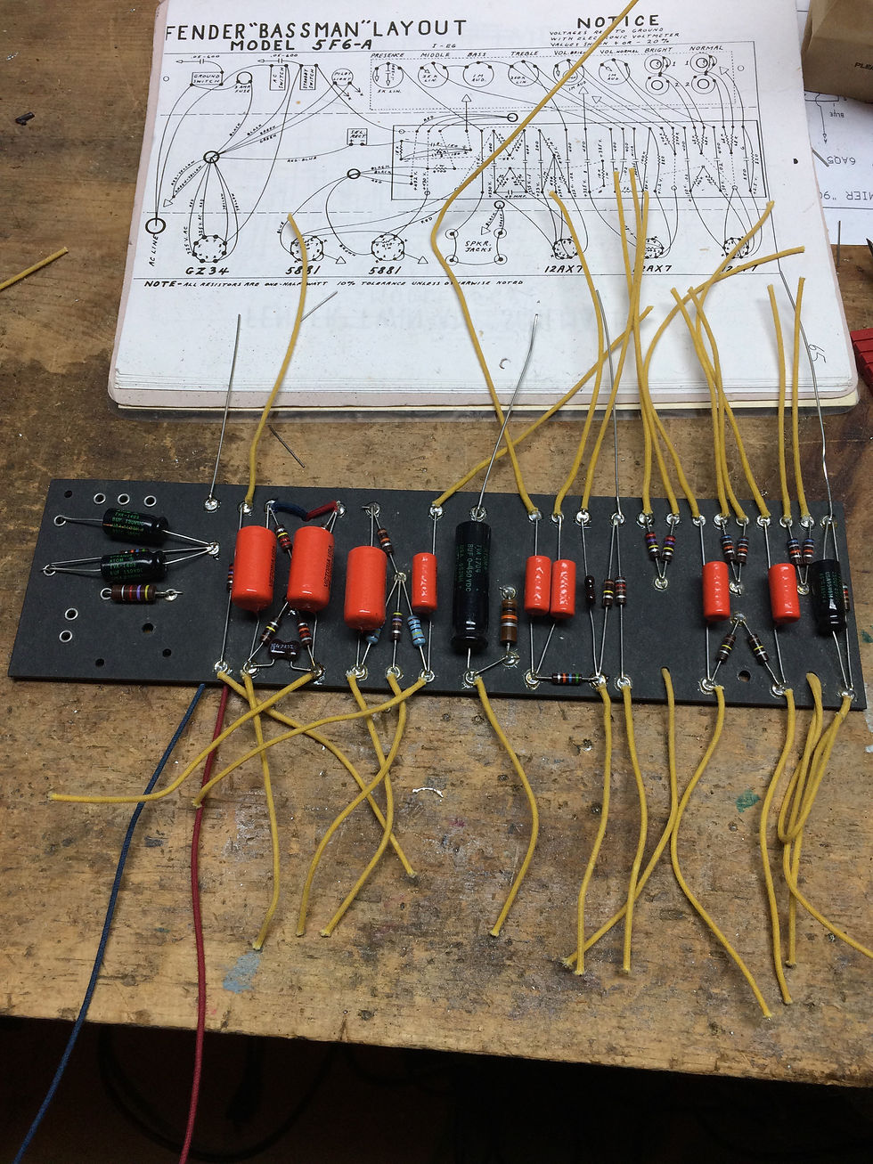
There's our eyelet board ready to go. I find running the leads ahead of time is just easier and neater. It is also how Fender did it, at least in their later days. I bought a surplus Twin Reverb board that was unused and it had all of its flying leads attached.

Happy filter caps on the eyelet board. Don't be vague, ask for Sprague! Their former factory in Massachusetts is now the site of Wilco's "Solid Sound" festival. The red & blue wires here are ones I made from white wire with sharpies. I think the black is too, come to think of it.
Mounted up

Test fitting the eyelet board to make sure the bias pot, transformer mounting bolts and so on won't interfere
Final location of the bias pot. Pretty happy with how it turned out.
Mounting the hardware now that everything has been fitted and drilled
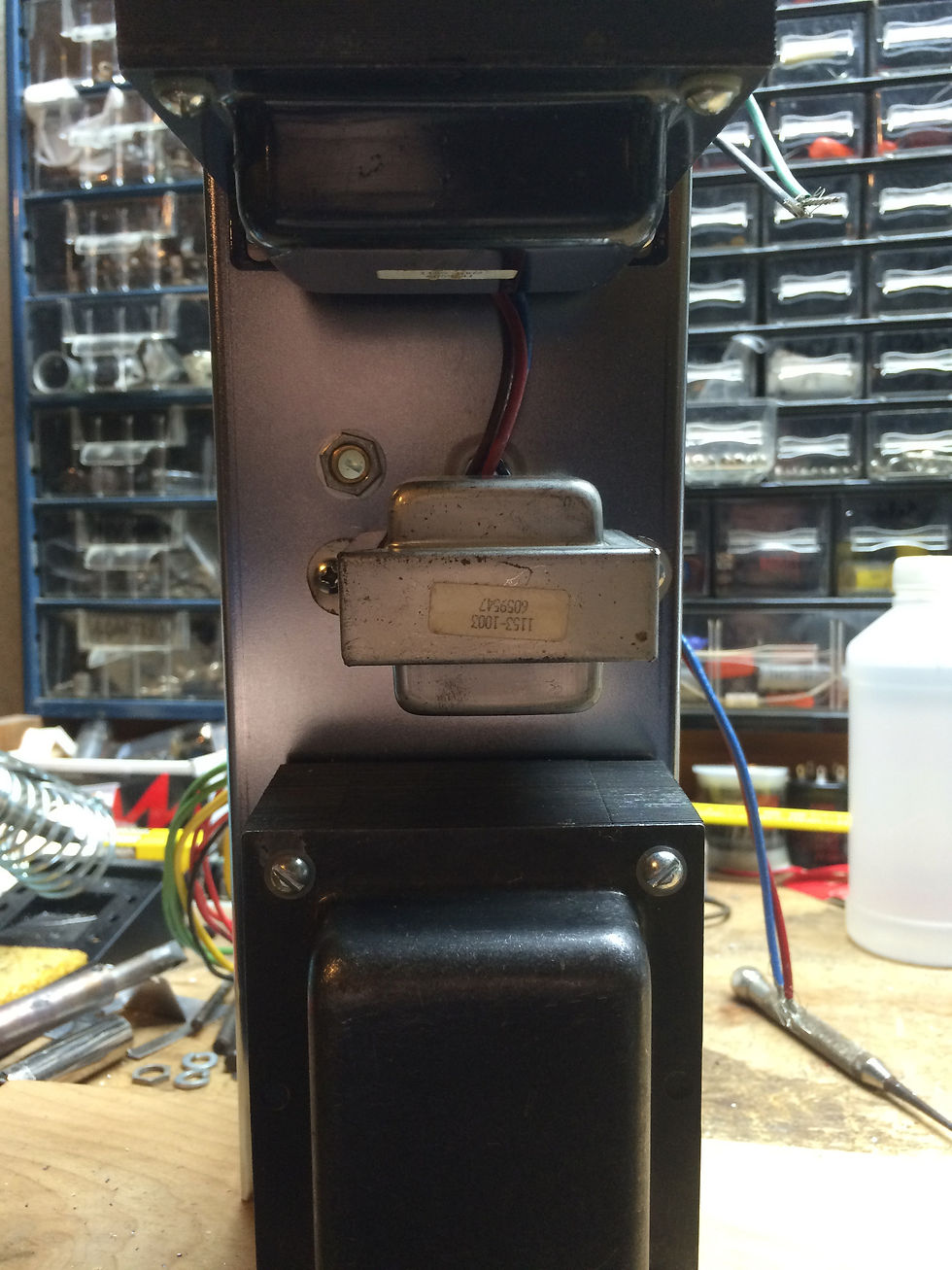
Building the power supply first so we can test it. It is the most critical and dangerous piece of the project. Making sure it's right before we go any further is just a good idea.

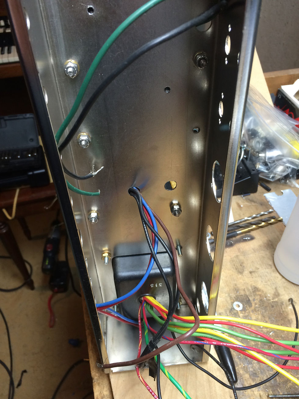
Looking good! One of the decisions you get to make with these reproductions is do you want it to sound like it did back then, or like an old amp does now? Line voltage was 110V back in the 50's and those amps now run higher than normal voltages on our 120+ wall voltage. I chose to make this amp run "as designed" on our modern voltages so the secondary is 315V-0-315 to give me 420-430V on the plates. It's a little less bright, a little more compressed. I'm very happy with it.

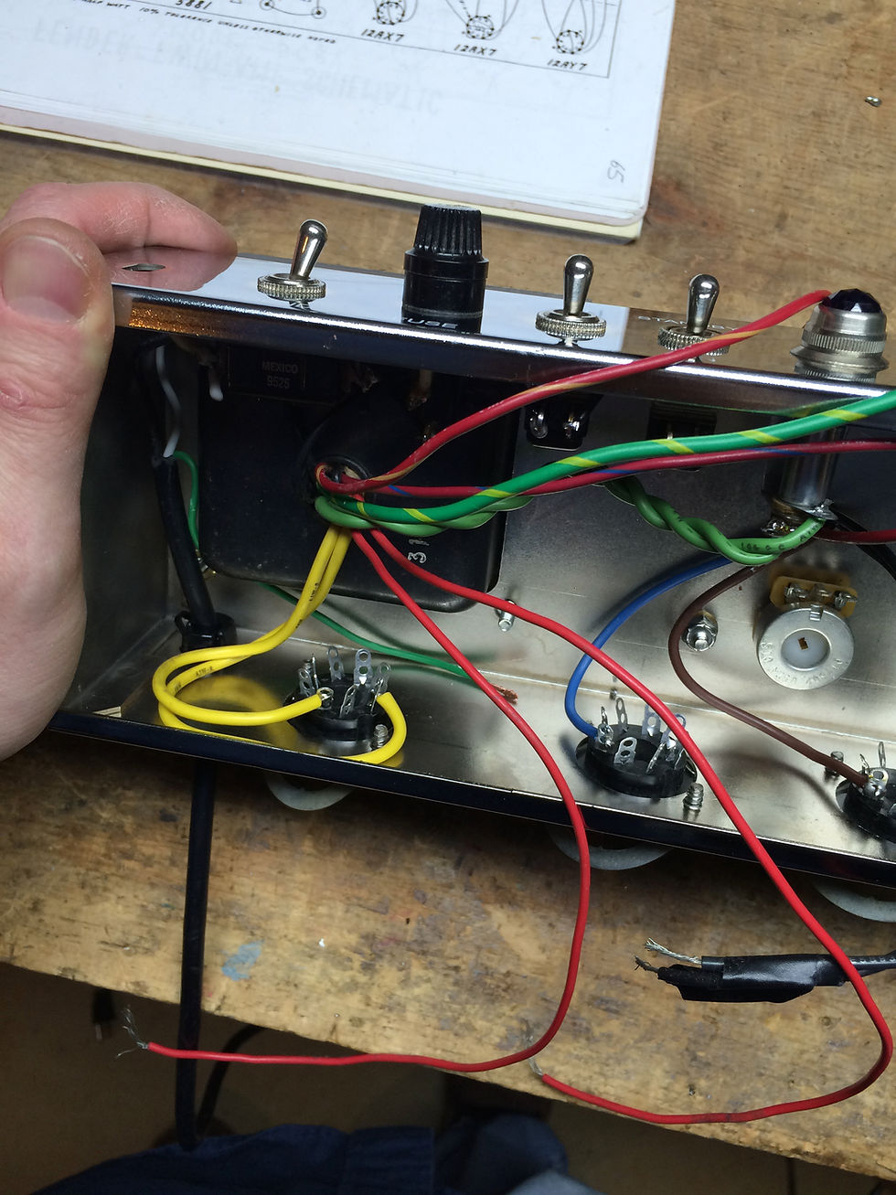
I was going to run the filaments up above the sockets until my smarter friends advised me to tuck them against the chassis as in the originals. It is neater, and easier. Having smart friends is a very good thing.

About halfway here. Sockets done, time to do the controls and input jacks.
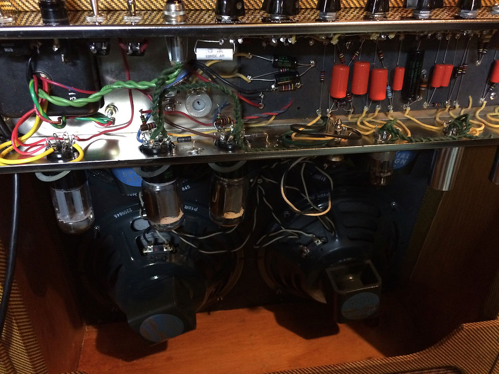
Testing the amp with a set of Recotron Jensens I was trying out while I waited for my Hammond re-cones to get finished.

Current state, post repairs to the phase inverter and now sporting the re-coned Jensens.
Kommentare